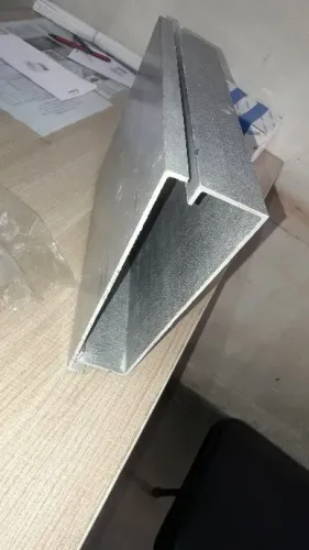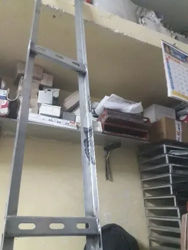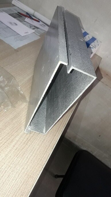
A damaged FRP cable tray can hide structural failure beneath an apparently minor surface mark, while removing it without supporting the cables can create a second fault. You will be able to inspect the complete support system, decide between isolation, repair and replacement, calculate the replacement capacity, and prepare a supplier request that matches the existing installation.
Key takeaways
- Inspect the tray, joints, supports and building attachments as one load path.
- Isolate damaged sections before moving cables or approving temporary support.
- Match tray width, depth, load rating, geometry and resin system before replacement.
- Give suppliers measurements, cable loads, damage photos and support details to verify.
Inspect the Entire FRP Tray and Its Support Path
Do not approve a damaged tray because its cables still appear supported. A frp cable tray for recovery must be assessed as a complete support path, from the cable load to the building structure, before anyone straightens, cuts or removes it.
- Isolate the affected circuit where required, stop further movement and install temporary supports before loosening tray hardware. Keep cable weight off damaged rungs, splice plates and side rails.
- Examine the tray body, side rails, rungs, splice plates, fasteners and covers for cracked or delaminated laminate, crushed sections, broken rungs, exposed fibres, heat damage and chemical attack.
- Check every support, anchor, hanger and bracket for distortion, pull-out, corrosion of attached hardware and loss of contact with the structure. A sound tray on a failed support path is still unsafe.
- Compare the remaining section with its original load rating and support span. Account for cable weight, tray dead weight, concentrated loads, environmental loads and temporary recovery loads; a visually similar section proves nothing.
- Inspect cables exposed to impact, crushing, heat, chemicals or excessive bending. Preserve the manufacturer’s minimum bend radius, prevent dragging over cut edges and arrange cable-specific mechanical and electrical testing; insulation resistance alone cannot confirm cable integrity.
- Confirm that grounding and bonding conductors remain independent. Nonconductive FRP does not perform the equipment-grounding-conductor function of an approved metallic tray.
Reject continued service when the laminate, supports or anchors cannot carry the calculated load, or when damage prevents secure cable support. Photograph and mark each defect before choosing isolation, repair or replacement.
Decide Whether to Isolate, Repair or Replace the Damaged Section
Isolate the affected circuit and provide temporary support before deciding what to do with the tray. Isolation is suitable only when the damaged section is taken out of service, cable weight is transferred safely, and sound tray and supports carry the remaining load without movement.
A splice plate restores continuity between sound sections; it does not restore a cracked, delaminated, crushed or permanently distorted rail. Use a structural repair only with a documented detail accepted by the original designer or a qualified FRP engineer. Do not apply a generic metal-tray repair method to FRP.
Require full FRP cable tray replacement when any of these conditions applies:
- A side rail, rung or base is cracked, delaminated, crushed, heat-damaged or permanently distorted.
- Fasteners have pulled out, splice connections cannot hold alignment, or supports or anchors have lost their capacity.
- The repaired section cannot meet the original load rating at the existing support span, including cable weight, tray weight, concentrated loads and temporary recovery loads.
- Fire, chemicals or impact have degraded the laminate beyond a verified repair detail.
- The replacement cannot preserve cable bend radius without dragging cables across sharp edges or overloading the tray.
FRP is electrically nonconductive. Keep the required grounding and bonding conductors independent of the tray; never assume it performs an equipment-grounding-conductor function. During recovery, use lifting supports or rollers and prevent sideways pulling on heavy cable bundles.
Recover the Cables Without Overloading the Replacement Tray
Do not pull a heavy cable bundle sideways across a damaged splice. Isolate the affected circuits where required, stop cable movement, and treat the replacement FRP cable tray as a support system—not a splice enclosure or cable-repair method.
- Record cable routes, labels, approximate weights and minimum bend radii before disturbing anything. Confirm the outage and isolation controls with the responsible electrical person.
- Install temporary lifting, rollers or independent supports beneath the cables before removing bolts, splice plates or damaged tray sections. Keep the load off the damaged tray and protect workers from exposed glass fibres.
- Remove sharp fragments and cover cut edges with suitable protection. Never drag a cable over an unprotected laminate edge.
- Transfer cables in controlled sections, maintaining each cable manufacturer’s minimum bend radius. Use enough rollers or lifting points to prevent a bundle from sagging, twisting or imposing a sideways load.
- Check the replacement tray’s allowable load against cable weight, tray dead weight, support spacing, concentrated loads and any temporary recovery load. Add supports before loading it if the calculation requires them.
- Secure cables in their final positions, then install splice hardware, covers and supports without trapping insulation or reducing separation.
- Verify grounding and bonding independently: FRP is electrically nonconductive and must not be assumed to provide an equipment-grounding-conductor path.
Photograph the completed transfer and retain the load check, cable identification and torque records. A documented frp cable tray for recovery protects the installation better than a visually similar section chosen under outage pressure.
Match Capacity, Geometry and Material Before Ordering
A replacement must match the original tray’s load path, not just its visible width and depth. Verify the cable load, tray dead weight, support span, concentrated loads and any temporary lifting load against the manufacturer’s rating.
| Check | Like-for-like FRP cable tray | Alternative tray type |
|---|---|---|
| Geometry | Width, depth, length, rung spacing, covers, fittings and splice-hole pattern | Confirm clearances, bend-radius space, cover fit and connection geometry |
| Structural data | Load class at the actual support span, including cable and tray weight | Obtain a documented rating for the same span and loading, not a nominal rating |
| Material | Resin system, glass reinforcement, temperature range and chemical resistance | Verify metal grade or polymer type, corrosion protection and temperature limits |
| Installation | Manufacturer-recommended splice plates, fasteners, anchors and support hardware | Check that the new hardware creates a continuous, verified load path |
| Electrical function | FRP is nonconductive and does not automatically provide equipment grounding | Preserve required grounding and bonding conductors independently |
Chemical exposure can explain the failure. Give FRP cable tray suppliers the actual chemical, concentration, temperature, exposure time and cleaning regime; acid, alkali, solvent and hydrocarbon service can affect resin systems differently.
Include marked-up dimensions, photographs, tray series, support spacing, cable inventory and approximate load. State the damage mechanism, fire or smoke requirement and outage window. This information lets FRP cable tray suppliers distinguish a true frp cable tray replacement from a redesigned recovery section without creating misaligned splices or an unverified load path.
Give Cable Tray Suppliers a Recovery Specification They Can Verify
Send a recovery pack, not just a width and one photograph. Cable tray suppliers need enough evidence to verify whether a proposed section matches the original load path, geometry and environment.
Include:
- Clear photographs of the damage, splice points, supports, covers and nearby tray, with a ruler in frame.
- Marked-up width, depth, length, rung spacing, splice-hole pattern and fitting dimensions.
- Tray series, manufacturer, resin system, laminate or surface treatment, if known.
- Support type and spacing, anchor details, cable load, tray dead weight, concentrated loads and temporary recovery loads.
- A cable schedule showing cable count, outside diameters, approximate weight and required bending radii.
- The damage mechanism: impact, overload, fire, chemical exposure or heat, including exposure duration and peak temperature.
- Ambient conditions such as outdoor ultraviolet exposure, moisture, temperature range and named chemicals.
- Required flame-spread, smoke, temperature and fire-resistance performance, plus the outage window.
FRP cable tray suppliers can then document a like-for-like replacement or explain why a redesigned section is necessary. Require resin, load class, support span, rung and cover geometry, splice hardware and chemical compatibility in the quotation; a visually identical tray from another system can leave the splice and load path unverified.
State that FRP is nonconductive. Preserve equipment-grounding and bonding conductors independently, and specify deburring, fibre-dust controls and compatible edge sealing for any field cut. If TIRUMALA ENTERPRISES is quoting, request these values on the submitted datasheet rather than accepting “FRP tray” as the specification.
Related product
 | All type FOR cable tray treading supplie View product → |
Frequently asked questions
What should you inspect after FRP cable tray damage?
Inspect the entire tray run, including splice plates, covers, bends, supports, fasteners and each attachment to the building structure.
When should you isolate, repair or replace a damaged FRP tray section?
Isolate the section first when stability or cable safety is uncertain. Repair only damage that preserves the tray’s structural capacity; replace sections with cracked, crushed, delaminated or permanently distorted members.
How do you recover cables without overloading the replacement tray?
Calculate the cable load, remove temporary loads, maintain bend radii and add supports before transferring cables. Confirm the replacement tray and supports carry the resulting load.
What information should you give FRP cable tray suppliers for a replacement?
Provide tray dimensions, straight and fitting geometry, cable types and weights, span lengths, support details, environment, damage photographs and the required material and load rating.