A ladder-tray quotation is incomplete when it says only “GI,” gives a sheet thickness, or lists kilograms per metre without a support span. By checking the galvanising process, usable dimensions, complete-system load rating, installation environment and supplier documentation, you can compare manufacturers on performance rather than appearance or nominal price.
Key takeaways
- Specify hot-dip galvanizing to ISO 1461 or ASTM A123/A123M.
- Calculate tray width from cable fill and required separation.
- Compare load ratings at your project’s actual support span.
- Request drawings, test data, coating records and installation details before ordering.
Define GI before comparing galvanising quality
GI in a project specification should mean galvanized steel, not “galvanized iron.” Define the base steel, galvanizing process, applicable standard, and whether coating occurs before or after tray fabrication. For fabricated ladder trays, hot-dip galvanizing to ISO 1461 or ASTM A123/A123M is a different requirement from electro-galvanizing; name the process instead of accepting “GI” alone.
| Option | What it means | What to compare |
|---|---|---|
| Hot-dip galvanized after fabrication | The completed tray is immersed in molten zinc, coating faces, edges and weld areas | ISO 1461 or ASTM A123/A123M certificate, coating uniformity and repaired damage |
| Electro-galvanized | Zinc is deposited electrically, usually producing a thinner, smoother coating | Product standard, stated corrosion exposure and suitability for the project environment |
| Pre-galvanized sheet | Steel is coated before cutting, punching and forming | Edge and cut-area protection, weld treatment and the sheet coating standard |
Do not rank quotations by a single figure such as “80 microns.” Ask GI cable tray manufacturers whether the number is a local minimum, average coating thickness or zinc mass per unit area; ISO 1461 and ASTM A123/A123M set acceptance values according to the steel article’s thickness.
Request the coating certificate, material certificate and stated inspection method.
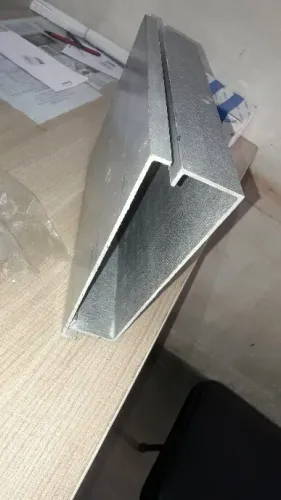
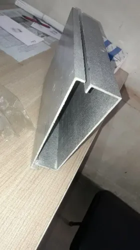
Inspect for bare patches, flaking, excessive zinc runs and uncoated welds. A photograph cannot prove coating compliance, and a thicker-looking surface does not replace documented corrosion-resistance requirements for the installation environment.
Size the ladder tray from the cable route, not the outside width
Measure the installed cable route before choosing tray size. Add the outside diameter of every cable, then apply the project’s fill rule; do not use the tray’s outside width as usable capacity. Keep separate allowances for control, power and communications cables where the installation code requires spacing or segregation.
| Selection | What to specify | What goes wrong if omitted |
|---|---|---|
| Width | Clear inside width, cable diameter, fill percentage and whether stacking is permitted | Cables spill over the rails or exceed the permitted fill |
| Depth | Clear usable depth below the highest rung, including cable cleats | Large cables foul covers, bends or side rails |
| Rungs | Rung spacing, profile, width and fixing method matched to cable diameter and cleat positions | Small cables sag between rungs or cleats cannot seat securely |
| Section length | Lengths that fit the support grid, access limits, route bends and joint locations | Excess joints increase labour and create alignment or bonding problems |
Choose the narrowest clear width that accommodates the calculated cable group plus the specified spare capacity. A deep tray does not compensate for insufficient width when cables must remain in one layer.
Select rung spacing from the cable diameter and securing method. Closely spaced rungs support smaller cables; wider spacing suits larger cables with cleats. Confirm this with the installation drawing.
Ask GI ladder type cable tray manufacturers for dimensional drawings showing clear dimensions, rung layout and section lengths. Request a route-specific take-off that separates straight sections from bends, tees, reducers and risers.
Compare load ratings at the actual support span
Check the rated load at the actual support span, not the tray’s steel thickness or a standalone figure in kilograms per metre. Enter the cable mass, fittings, cleats, fire-rated cables and reserved future capacity in the support calculation, then compare that total with the ladder tray and support rating.
| Rating basis | What it proves | What to verify |
|---|---|---|
| Catalogue load at a stated span | Capacity under the manufacturer’s test arrangement | Confirm the span matches your support spacing |
| Uniformly distributed load | Capacity for evenly spread cable weight | Add point loads from cleats, fittings and equipment |
| Complete system rating | Performance of tray, joints, bends and supports | Request IEC 61537 test or design-validation evidence |
| NEMA VE 1 classification | Working load linked to a defined support span | Reject any rating that omits the test span |
A quotation from GI cable tray manufacturers is incomplete if it gives only “100 kg/m” without the span, allowable deflection and loading pattern. Ask for the load/span table, calculation method and the maximum deflection at your actual spacing; then check the supports, anchors, splice plates, bends, tees, reducers and vertical fittings as one assembly.
For a ladder tray, verify these points before approval:
- Apply the heaviest cable arrangement, not an average route weight.
- Include the specified percentage of future capacity as a real load.
- Check concentrated loads separately from distributed loads.
- Confirm long outdoor runs include expansion provisions so thermal movement does not load supports or connected equipment.
Match ladder construction to the environment and cable-support method
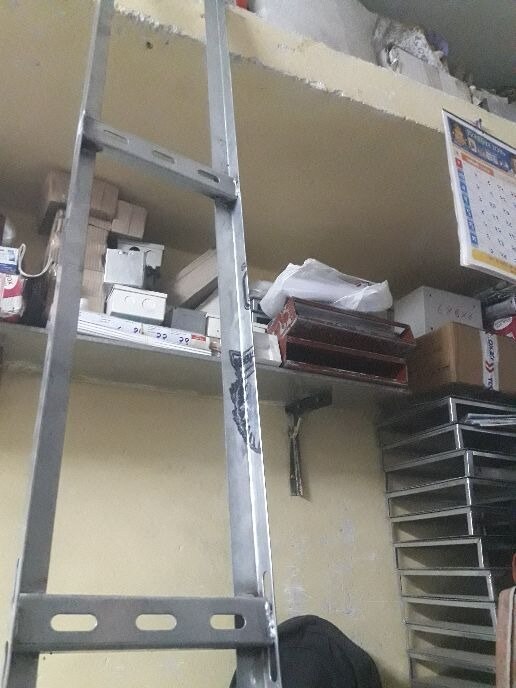
Ladder tray suits ventilated, inspectable routes carrying power or control cables where water drainage and easy cable placement matter. Its open rails do not provide weather shielding, fire separation or electromagnetic screening, so add covers and barriers or select another containment where the specification demands them.
Outdoor runs also need calculated expansion joints; a rigid tray must not restrain movement-sensitive cables or connected equipment.
| Option | Best use | Main limitation |
|---|---|---|
| Ladder tray | Ventilated indoor or outdoor cable routes with cleats or ties | Does not protect against impact, fire spread or weather |
| Perforated tray | Smaller control, instrumentation and power cables needing a continuous support surface | Holds water and dirt more readily than ladder tray |
| Solid-bottom tray | Fine cables, heavy dust, falling debris or a barrier beneath the route | Reduces ventilation and can retain water unless drained |
| Wire-mesh containment | Light control, data and telecom cables with frequent route changes | Lower protection and load capability; unsuitable for heavy cables without verification |
On horizontal runs, lay cables without sharp crossovers and secure them to rungs or the tray base with UV-resistant ties, stainless bands or approved cleats. Space restraints to stop sliding and separation at bends, tees and risers; do not crush the sheath.
On vertical runs, provide cleats or clamps sized for cable diameter and short-circuit forces. Tray rungs alone are not a vertical restraint. Single-core AC cables need a cleat arrangement and material selected for the fault-force calculation, with non-magnetic hardware where the design requires it.
Ask gi ladder cable tray suppliers for the restraint method and installation spacing, not just the tray dimensions.
Request a complete manufacturer dossier before placing the order
Ask GI ladder cable tray suppliers for a dossier, not a photograph and sheet-gauge statement. The file should identify the material and galvanising process, cite the coating standard used, and include a coating certificate, material certificate, dimensional drawings and installation instructions.
Request these documents and confirmations before accepting the quotation:
- Type-test or design-validation evidence for the complete system under IEC 61537, including straight trays, bends, tees, crosses, reducers, risers, splice plates and supports.
- A load/span table stating working load, support span, allowable deflection and the calculation method for horizontal and vertical runs. A kilograms-per-metre figure without its test span is incomplete; NEMA VE 1 classifications also depend on working load and span.
- An accessory schedule with separate quantities and prices for bends, tees, reducers, risers, covers, hold-down clamps, splice kits, hangers, bonding jumpers and seismic restraints.
- Electrical-continuity results or a bonding arrangement showing jumper locations across joints, expansion gaps, painted interfaces and flexible connections.
- Project drawings confirming tray widths, side-rail heights, rung spacing, section lengths, route elevations, cable segregation, covers, barriers and support spacing.
Use this comparison to test what the quotation actually proves:
| Evidence | Acceptable confirmation | Red flag |
|---|---|---|
| Coating | Certificate naming coating mass or thickness and standard | “GI finish” only |
| Load | System rating at your specified span | Tray width or thickness alone |
| Continuity | Tested joint path or specified jumpers | Earthing left unstated |
TIRUMALA ENTERPRISES should be asked for the same dossier when its ladder trays are being considered; a complete file makes its offer comparable with other GI cable tray manufacturers.
Related product
 | Reliance type tray manufactur we are View product → |
Frequently asked questions
What does GI mean for a ladder cable tray?
GI should identify galvanized steel, with the base steel, galvanizing process, standard and fabrication sequence stated. Hot-dip galvanizing to ISO 1461 or ASTM A123/A123M differs from electro-galvanizing.
How do you choose the correct ladder tray size?
Measure the cable route and cable grouping, then calculate usable width, fill, separation, bend space and future capacity. Do not select a tray from its outside width alone.
How should you compare ladder tray load ratings?
Compare each manufacturer’s stated load at the support span your project uses. A rating at 1.5 metres cannot be treated as the rating at 2.4 metres without supporting data.
What documents should GI cable tray manufacturers provide?
Request dimensional drawings, material and galvanizing specifications, load tables for the actual span, joint and support details, coating records, test reports and installation instructions.