“GI” alone does not tell you how a perforated cable tray was galvanized, how much load it can carry, or whether its fittings will remain electrically continuous. By the end, you will be able to define the tray system, calculate a usable size, compare competing tray formats, and assess quotations from manufacturers and suppliers on delivered performance rather than straight-length price.
Key takeaways
- Demand tray thickness, finish, accessories, supports and bonding parts in every quotation.
- Size for cable fill, load, support spacing and planned future capacity.
- Choose perforated GI tray when ventilation, routing flexibility and inspection access matter.
- Reject GI perforated tray for corrosive, fire-rated or fully enclosed routing conditions.
What a GI perforated cable tray quotation must actually describe
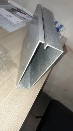
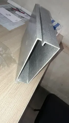
A quotation that says “GI tray” is incomplete. It must describe the complete system: perforated base, side rails, straight lengths, bends, tees, reducers, covers, couplers or splice plates, supports, clamps, separators and bonding parts. Otherwise, two GI perforated cable tray manufacturers may quote different products under the same line item.
- Require the quotation to identify the tray and every fitting, including dimensions, steel thickness, perforation pattern, support hardware and bonding parts.
- Require the finish to state whether the tray uses pre-galvanized sheet or hot-dip galvanizing after fabrication. Name the steel standard, coating designation or minimum thickness, and whether that requirement applies before or after cutting, punching and welding. ASTM A653 designations such as G90 describe zinc-coated sheet supplied to that sheet standard; ASTM A123 and ISO 1461 address fabricated hot-dip-galvanized articles. For ISO 1461, minimum average coating thicknesses are 45 µm below 1.5 mm steel, 55 µm at 1.5–3 mm, 70 µm at 3–6 mm and 85 µm above 6 mm.
- Ask how the finish protects cut edges, punched holes and welds. Pre-galvanized fabrication exposes or damages coating at these locations, while post-fabrication galvanizing coats accessible finished surfaces. Require ASTM A780-qualified zinc-rich repair for damaged hot-dip-galvanized areas.
Use this same schedule when comparing GI cable tray manufacturers. It prevents a low price per metre from hiding missing fittings, splice hardware, supports or coating requirements.
How to size the tray for cables, supports and future capacity
Start with a cable schedule, not a tray catalogue. For every power, control, instrumentation, data and fire-alarm cable, record outside diameter, quantity, weight per metre, minimum bending radius and required separation. Calculate the occupied width or arrangement, add the specified future spare capacity, then check the bend radius at bends, tees and reducers.
- Use the manufacturer’s usable internal width and height, not the nominal outside tray width.
- Do not apply a universal 40% fill rule: check cable grouping, thermal or ampacity limits and project-specific separation.
- Verify total cable weight plus covers, separators, wind or ice loads where applicable, and concentrated loads from power or control cables.
- Select steel thickness and support spacing from load-versus-span data for the complete tray system.
| Selection item | What to verify | What goes wrong if missed |
|---|---|---|
| Width and height | Internal dimensions, cable arrangement and future space | Overcrowding or unusable bend space |
| Steel thickness | Perforation pattern, side-rail height, material strength and splice design | Gauge alone gives a false capacity estimate |
| Support spacing | Uniformly distributed load at the stated span and support type | Deflection or failure on a longer span |
| Special loading | Cantilever, point loads, covers, separators, wind and ice | A catalogue rating no longer applies |
Ask perforated cable tray manufacturers and gi perforated cable tray suppliers for load tables covering the complete tray, fittings, splice design and support type. Require deflection limits separately, with distinct data for cantilever and point-load conditions.
When perforated GI tray beats other cable-support formats
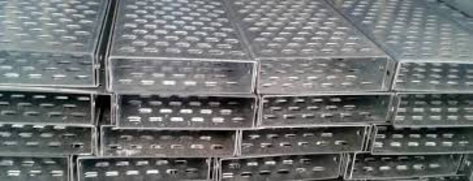
A perforated GI tray is the practical default around panels, machines, distribution boards, plant rooms, warehouses and commercial buildings when you need ventilation, drainage and frequent cable tie points without losing continuous cable support.
Its perforated base and side rails support cables along their length more consistently than ladder rungs, while bends, tees, reducers, covers, couplers, supports and clamps create a repeatable equipment-routing system.
| Format | Advantage | Choose it when |
|---|---|---|
| Ladder tray | Maximum ventilation and high load clearance | Heavy, large-diameter or heat-producing cables need open air |
| Solid-bottom tray | Better containment and small-cable retention | Small control, instrumentation or data cables could fall through perforations |
| Wire-mesh tray | Low weight and rapid routing | Light cable groups need quick site changes |
| FRP tray | Non-metallic, corrosion-resistant construction | Chemicals or aggressive corrosion rule out metal |
| Aluminium raceway | Low weight and corrosion resistance in an enclosed form | You need lighter, more enclosed containment |
Use covers, clamps or ties on vertical and inclined runs; perforations alone do not retain cables. They also do not establish ampacity, electromagnetic compatibility or fire performance. Cable construction, spacing, grouping, bonding and cover use determine those outcomes.
Equipment suppliers value matching tray-and-fitting systems because installation is faster and mechanical capacity remains traceable. Do not mix generic bends or splice kits with another manufacturer’s tray: nominal dimensions can match while load capacity and electrical continuity do not.
Compare complete systems from GI cable tray manufacturers and request tested compatibility from perforated cable tray manufacturers.
Where GI perforated tray is the wrong specification
Redirect the specification when the atmosphere can consume zinc faster than the tray can protect itself. High-corrosion chemical areas, chloride-rich coastal sites, sulfur compounds, persistent moisture and high temperatures all demand an exposure review. Contact with dissimilar metals can accelerate corrosion at the joint.
GI perforated cable tray suppliers must state environmental suitability and offer a coating or material upgrade; “galvanized” alone is not an approval.
- Use a screened or enclosed system where electrical shielding, controlled ingress protection or protection from conductive contamination is required.
- Choose FRP where corrosion resistance, electrical insulation or non-metallic supports is essential.
- Specify engineered supports for exceptionally heavy cable runs, concentrated loads or spans beyond the tray’s published capacity.
- Use solid-bottom containment where small cables need retention, falling contamination must be reduced or the installation needs more enclosure than perforations provide.
- For outdoor trays, check wind, ice, drainage, thermal movement and coating damage at cuts, holes, bends and supports.
A cover blocks falling dust and debris, but it does not automatically create a certified IP enclosure. Require the stated IP rating and test basis if ingress protection matters.
Electrical continuity is a design requirement, not an afterthought. Require GI cable tray manufacturers to document joint resistance, splice hardware, bonding jumpers where needed, and zinc or paint removal at contact points. Require measured results against the project limit and reference IEC 61537, which addresses cable-tray electrical continuity and testing.
A mechanically complete tray can still fail as a bonding path.
How equipment suppliers should compare manufacturers and accept the system
Compare the complete installed system, not the straight-tray rate. Your cost must include straight tray, bends, tees, reducers, covers, splice plates, supports, separators, bonding parts, packing, site repairs and installation effort.
| Cost item | Check before comparison | Why it matters |
|---|---|---|
| Straight tray | Width, height, thickness and quantity | Nominal metre price hides size differences |
| Fittings | Bends, tees, reducers and covers | Missing fittings create site fabrication and delays |
| Hardware | Supports, couplers, separators and bonding parts | Generic replacements can change capacity and continuity |
| Installation | Packing, handling, repairs and labour | Damage and complex assembly increase delivered cost |
Before approval, ask each gi perforated cable tray manufacturers for:
- Dimensional inspection records and steel or mill certificates.
- Coating certificates or coating-thickness readings, with the finish process and governing standard named.
- Load tables showing allowable load against support span for the complete tray, including the stated deflection limit.
- Fitting, coupler and splice details, plus continuity or bonding information.
- Confirmation that tray, fittings, supports and couplers form one specified or tested system.
Your purchase order must name tray width and height, steel thickness, perforation pattern, finish process, governing standard, coating requirement, support span, allowable load and deflection limit. Do not accept a generic “GI tray” line item.
Use the same checklist with gi perforated cable tray suppliers, including TIRUMALA ENTERPRISES, when requesting a complete package for panels, machines or plant installations in Pune or Maharashtra. A catalogue photograph cannot prove interchangeability, capacity or electrical continuity.
Related product
 | GI Perforated Cable Tray View product → |
Frequently asked questions
What must a GI perforated cable tray quotation describe?
It must identify the perforated base, side rails, straight lengths, bends, tees, reducers, covers, couplers or splice plates, supports, clamps, separators and bonding parts, along with material, dimensions, thickness and finish.
How do you size a GI perforated cable tray?
Calculate the cables’ occupied width and weight, check the manufacturer’s load table at the specified support spacing, and reserve capacity for future cables without exceeding the permitted fill or deflection.
When does perforated GI tray beat other cable-support formats?
It suits routes that need ventilation, visible cable inspection, flexible cable entry and easier additions than enclosed trunking or solid-bottom tray.
When is GI perforated tray the wrong specification?
Use another system when the route requires high corrosion resistance, fire-rated cable protection, strong ingress protection or a fully enclosed barrier against dust, water or mechanical impact.