A quotation for “GI cable tray” is incomplete until it identifies the zinc coating, tray geometry, working load, support span and fittings included. By the end, you will be able to compare Nashik manufacturers, size a tray for your cables, and check whether the proposed system is suitable for the site environment and installation method.
Key takeaways
- Specify base-steel thickness and zinc coating mass in every quotation.
- Keep tray fill within usable width after accounting for cable spacing.
- Match supports, bends and fasteners to the tray’s rated load.
- Record continuity, coating repairs and inspection documents before handover.
What GI means, and which galvanising finish suits a Nashik site
GI means galvanized steel, not solid iron: a zinc coating protects the steel from moisture and delays rust. Ask GI cable tray manufacturers in Nashik to identify the base-steel thickness, zinc coating specification or measured coating mass, and the inspection document supplied with each batch.
Pre-galvanized sheet receives zinc before it is cut, punched and formed. Cut edges, drilled holes and weld zones can have less zinc protection. Hot-dip galvanizing after fabrication immerses the completed tray and covers those exposed areas, making it the stronger choice for an outdoor, damp, wash-down or chemically aggressive Nashik location.
| Finish | What happens | Suitable use |
|---|---|---|
| Pre-galvanized | Zinc coating is applied before fabrication; fabricated edges need attention | Clean, dry indoor routes where cut-edge protection is specified |
| Post-fabrication hot-dip galvanized | Completed tray, holes, cuts and weld areas receive the zinc coating | Outdoor, humid, wet or exposed installations |
| FRP alternative | Non-metallic tray avoids steel-zinc corrosion, but has different load and earthing requirements | Highly corrosive areas where the design accepts FRP limitations |
Before selecting, confirm these corrosion details in the quotation:
- Fastener material or coating, washers, splice-plate resistance and the repair method for site-damaged zinc.
- Isolation or compatible plated hardware where copper, brass or aluminium touches the tray; moisture can cause galvanic corrosion.
- Whether the tray is intended to provide electrical continuity. A separate protective conductor is required when joint continuity or fault-current capacity is not assured.
Choosing the tray type and calculating usable capacity
Choose the tray form from the cable’s heat, weight, protection and bending needs, not from width alone. A GI cable tray for installation projects suits ordinary indoor and outdoor runs, while FRP is better where chemicals, persistent moisture or electrical non-conductivity governs the choice.
| Form | Best fit | Check before sizing |
|---|---|---|
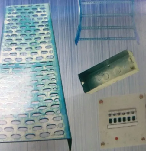
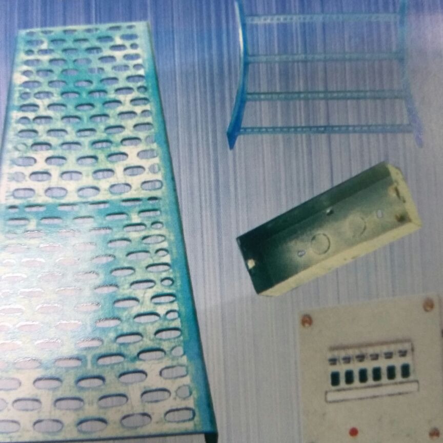
| Perforated tray | Power, control and mixed cables needing ventilation | Hole pattern, edge protection and cable support at bends |
| Ladder tray | Heavy power, large single-core or long runs | Rung spacing, cable cleats and concentrated load at rollers |
| Solid-bottom tray | Small control or instrumentation cables needing debris protection | Heat dissipation, drainage and inspection access |
| FRP tray | Corrosive areas or where insulation from the support is required | Fire performance, UV rating and mechanical load |
Calculate usable capacity from each cable’s actual outside diameter. Add the required separation between circuits, preserve the largest cable’s minimum bending radius at every bend, and reserve the project’s stated allowance for future cables; do not apply a universal 40% or 50% fill rule.
Specify clear internal width, side-rail height, material thickness, straight length, rung spacing and hole pattern. Then confirm the selected series’ working load and support span for your cable mass. A 300 mm tray with 50 mm rails is not equivalent to one with 100 mm rails, even at the same width.
Request bends, tees and reducers with dimensions that preserve bending radius and load continuity.
Fittings, supports and load limits that affect installation
A tray’s allowable load depends on width, side-rail height, steel thickness, rung pattern, support span, splice position and cable placement. Require a load-versus-span table or tested load class from GI ladder cable tray suppliers; a nominal thickness alone cannot prove that a span will carry your cables without deflection.
Specify the complete system before comparing quotations:
- Straight sections with internal width, side-rail height, material thickness, length, rung spacing and working load
- Bends, tees, reducers and risers with fitting radius, reinforcement and any reduced load rating
- Splice plates, bolts, bonding jumpers and covers matched to the tray series
- Cantilever brackets, trapeze supports, threaded rods, anchors and vertical-run clamps
- Maximum support span, allowable splice location and extra support requirements at fittings, rollers and concentrated cable loads
- Coating process, finished mass and dimensional tolerances
Set support spacing from the supplier’s load table and your actual cable weight, not from tray width alone. Heavy single-core cables, long spans, vertical runs and seismic restraint require closer supports or a stronger tray series. Place joints near supports only when the manufacturer permits it.
Keep the cable’s minimum bending radius through every bend, tee and reducer. Ladder tray suits large power cables because it ventilates and drains; perforated or solid-bottom tray supports small control cables continuously. At wall and floor penetrations, install a tested fire-stop system rated for the cable bundle and opening.
Ordinary mortar or loose mineral wool is not an equivalent substitute.
How to compare GI cable tray manufacturers in Nashik quotations
Compare quotations only after every GI cable tray manufacturers in Nashik receives the same technical schedule. A metre rate can hide a narrower tray, lighter steel, fewer fittings, or a lower load rating. Reference IEC 61537 and require deviations in writing.
| Quote item | Require from each vendor | Why it changes the comparison |
|---|---|---|
| Geometry | Internal width, side-rail height, length, rung spacing, hole pattern and dimensional tolerances | These determine usable cable space and installation fit |
| Steel and coating | Thickness, unit mass, coating process, zinc mass or coating class, and whether steel is pre-galvanised or hot-dip galvanised after fabrication | Post-fabrication galvanising coats cut edges, holes and welds |
| Strength | Load-versus-span table or tested load class, splice position, support spacing and concentrated-load limits | Capacity depends on geometry, span and cable position, not thickness alone |
| Fittings | Bend radius, tee and reducer dimensions, reinforcement, cover type and fitting load rating | Straight-tray ratings do not automatically apply to fittings |
| System hardware | Splice plates, fasteners, support steel, bonding jumpers and continuity provisions | Missing components create installation delays and extra costs |
| Commercial terms | Quantity basis, standard lengths, fitting counts, freight, taxes, delivery date, warranty and replacement terms | A low ex-works price can become the highest installed cost |
Ask GI ladder cable tray suppliers to price the complete bill of materials, not just straight sections. Include extra supports for long or vertical runs, heavy single-core cables, seismic restraint and cable-roller loads.
Give TIRUMALA ENTERPRISES the same schedule and request a marked technical compliance sheet; compare every exception before accepting its quotation. A quote without IEC 61537 identification, load data or coating details is incomplete, regardless of its price.
Related products
 | ₹140 View product → |
 | GI Perforated Cable Tray View product → |
Site checks for continuity, corrosion repairs and safe handover
Verify the supplied system against the approved drawings, purchase specification and IEC 61537 before energisation. Check tray width, side-rail height, thickness, hole pattern, fittings, covers, support locations and cable routing; a catalogue match on width alone does not prove compliance.
Use this site checklist:
- Measure support spacing and inspect deflection at straight runs, bends, risers and concentrated cable-roller loads. Add supports where the installed load or vertical run exceeds the design basis.
- Confirm every joint is mechanically tight and electrically continuous. Test across representative tray sections and record the instrument, locations and results; do not assume the tray is a protective conductor unless the electrical design says so.
- Inspect site-cut, drilled and ground areas for exposed steel. Remove loose zinc and contamination, then apply the specified zinc-rich repair paint or approved zinc-repair process. Ordinary aluminium or bituminous paint is not an equivalent repair.
- Check covers for secure fit, ventilation and inspection access. A covered GI cable tray for installation projects can restrict heat dissipation and affect cable ampacity.
- Inspect wall and floor penetrations for a tested fire-stop system matched to the cable bundle and opening size. Mortar or loose mineral wool alone does not provide a rated seal.
Handover should include marked-up as-built drawings, continuity records, coating-repair locations, support inspection notes, product certificates and fire-stop records. Confirm the final cable fill, bend radii and spare capacity against the approved calculation before accepting the gi cable tray for installation projects.
Frequently asked questions
What does GI mean in a cable tray, and which finish suits Nashik?
GI means galvanized steel, with a zinc coating that protects the steel from moisture. Specify the base-steel thickness, zinc coating specification or measured coating mass, and batch inspection documents. Select the finish against the site’s exposure to rain, humidity, chemicals and indoor or outdoor installation conditions.
How do you calculate usable capacity for a GI cable tray?
Use the tray’s internal width and depth, then allow space for cable spacing, bending radius, heat dissipation and future additions. Do not calculate capacity from the outside dimensions or fill the tray edge to edge.
Which fittings and supports affect a GI cable tray installation?
Include bends, tees, crosses, reducers, couplers, covers, hangers and support channels in the design. Set support spacing and load limits from the manufacturer’s tested rating, cable weight and site conditions.
How should you compare GI cable tray manufacturers in Nashik quotations?
Compare steel thickness, zinc coating specification or measured mass, tray type, dimensions, load data, fittings, support details, delivery scope, inspection documents and warranty terms. Check that each quotation describes the same usable dimensions and finish.
What site checks are needed before handing over a GI cable tray system?
Inspect joints, fasteners, sharp edges, bends, supports, covers and coating damage. Repair exposed steel with a compatible zinc-rich repair coating, verify electrical continuity across joints, and record test results, repairs and batch documents.
Related product
 | Reliance type tray manufactur we are View product → |